Equipment
In several years of practice, we have already realized numerous design variations and with them, developed a whole lot of standard solutions and discovered special solutions. And if all that does not fit, we will also be glad to develop a system absolutely for your individual needs because there’s no such thing as “doesn’t work”. The following is a brief overview of the major components of our rail lubrication systems.
- Standard construction form
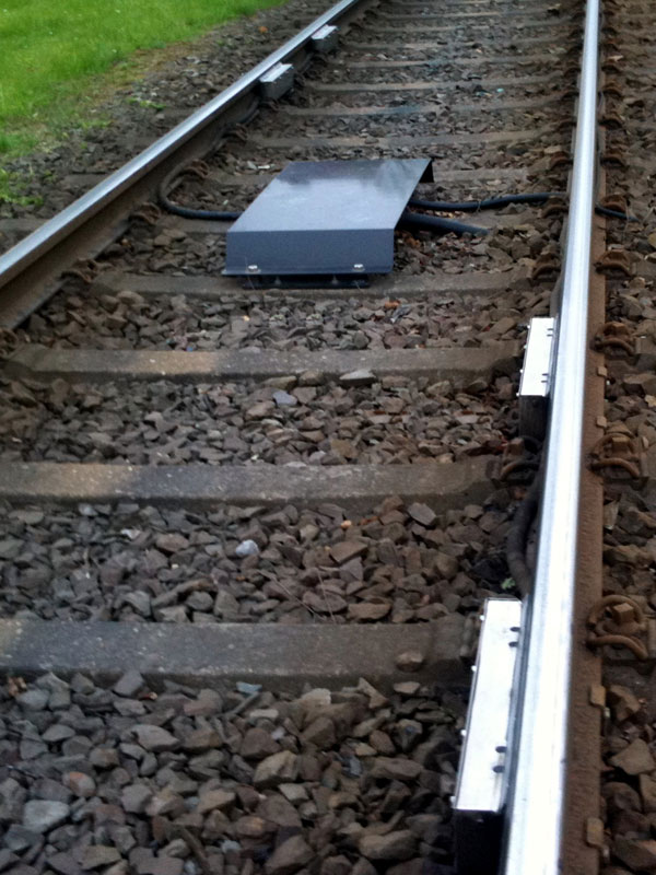
 The installation core is placed in direct proximity to the lubrication path.
- Construction form Bus system
The installation core can be placed up to 120 m away from the lubrication path. In this construction form, several lubrication paths can be operated with just one installation core.
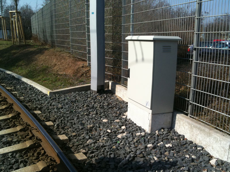
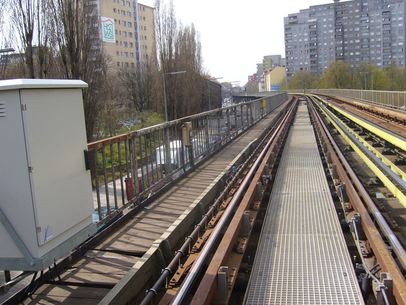
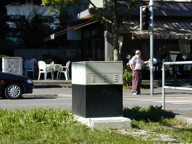
- Cabinet design with one or two grease storage mechanism
The housing cabinet is mounted on a foundation, a base plate or a lightweight concrete base. If there is no place to mount it, it can also be installed with wall fastening.

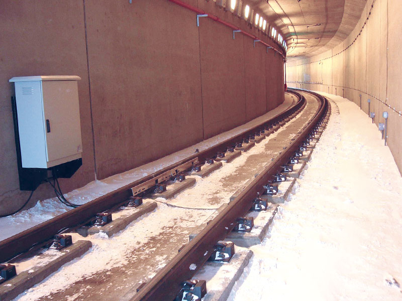
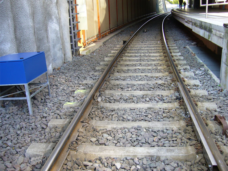
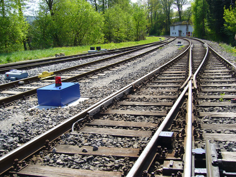
- Box design with one or two grease storage mechanism
The system box can be installed beside the rail track facility on a foundation base or an assembly pedestal, or concealed underground in an earth box in the middle of the rail track or beside the track facility.

- Underground lift with one or two grease reservoirs
The installation core is mounted on a plate in a steel container concealed underground and covered with a waterproof cover. For maintenance works, the installation core with cover will be run up by electro-hydraulic means. The waterproof cover can be plastered individually (e.g. cobblestone pavement), even strict government construction conditions can be met by this means.

- Plate design with one or two grease reservoirs
This design can be installed either in any available room or in any cabinet provided by the operator.
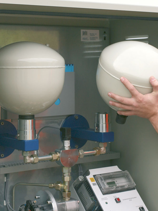 In every design variation the bio-degradable lubricant is stored in maintenance-friendly, refillable interchangeable reservoirs with diaphragm technology. The maximum weight of 16 kg per container makes it easy to transport them also to hardly accessible locations.
Facilities with two grease reservoirs are fitted with a special interchangeable valve to facilitate the changing of the container itself also during operation. The containers are screwed onto an adapter with its cover opening automatically and shutting likewise when unscrewed. This also prevents the facility from being soiled with lubricants and other dirt of the lubricant that are capable of causing operational faults while changing the container.
The containers are available in sizes of 12 liters (effective volume 9 l) and 5 liters (effective volume 3.75 l). The high operating pressure of 16 bar and the emptying rate in excess of 95% ensure optimal economic feasibility.
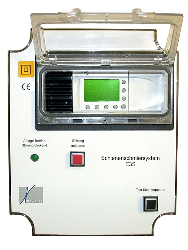 The system is controlled by an integrated small controller (PCL) that is placed in a compact switch cabinet with all switching and connecting components. Operating status and parameters are shown on a display. All entries are made through a key panel. There is a potential-free interface for the transfer of the signal Operation/Fault as well as contact for On/Off switching in the basic equipment.
Other equipment characteristics are optionally available:
- Temperature controlDifferent amounts of grease and lubrication intervals can be set for the outdoor temperature that fluctuates on daily and seasonal basis.
- Function controlGrease ejection in the lubrication channels is monitored. Irregularities are displayed and reported.
- BCD coding Operational and fault reports are transmitted to a customer-specific process control system through the BCD interface.
- GSM technology Communication between the system and the operator can be made by SMS or email. All operating status can be requested by this means; on the other hand, the system sends out alert messages all on its own (e.g. grease stock running out). A chain of alarms can also be programmed for this purpose. The installed modem is capable of establishing contact with all devices that are suited for digital data processing.
- Solar technology24 V/DC with controller, battery monitoring system with deep discharge protection, two panels on mast fastening pedestal.

- Voltage converter
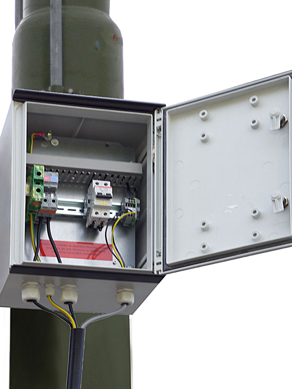
 DC/DC converter for connection with overhead traction line; Nominal voltage 600 V/DC (400 V – 950 V/DC). The voltage converter can be placed in the installation core (only in cabinet models) or in outdoor casing for fastening to a mast.
- Battery packFor installation without power supply lines. With controller for protection against deep discharge, the batteries are replaced at the same time as the grease storage system and can be recharged. The battery pack is integrated in the installation core (possible with only one grease storage system in the box model).
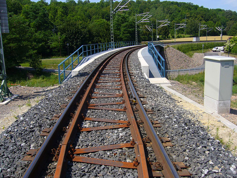
- Earth box as housing for installation coreThis is available in two designs: It is embedded in the flanges of the rail after being insulated against leakage current for installation in the middle of the tracks, the operator provides an adequate concrete foundation for installation beside the track system. The earth box is then connected to the track drainage system with a drainage support system.

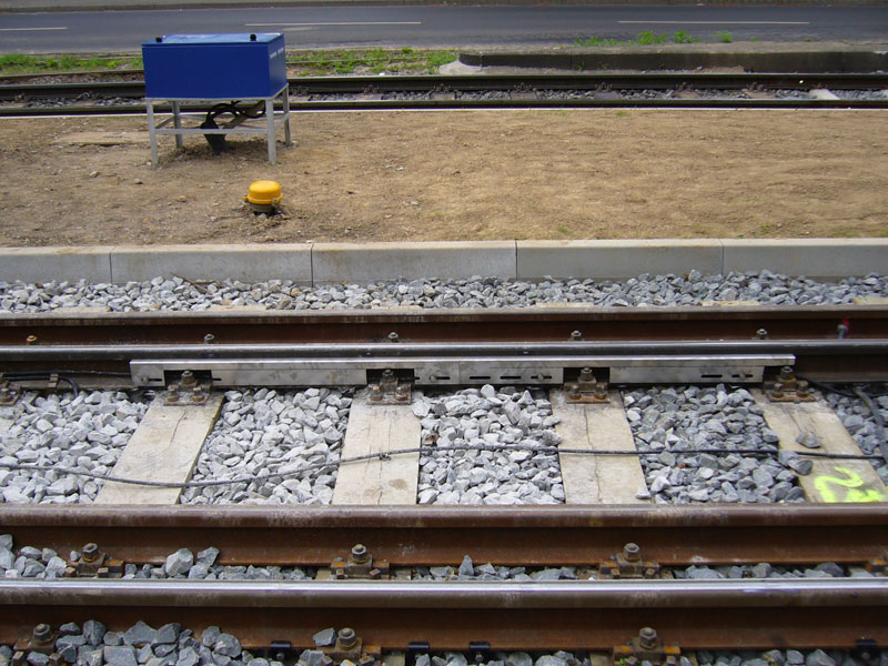
- Distributor box for the installation of hydraulic components, sensors and distributorsThey are placed in the middle of the rails, they are either fastened to the cross ties (mostly in vignol tracks) or are embedded in the flanges of the rail after insulation against leakage current. The boxes designed for the area covered have a drainage support system with which they can be attached to the drainage system of the rails.
- Review boxes for the installation of hydraulic componentsConnection hoses are installed unalterably. Inspection boxes for use on vignol tracks have an open base plate for drainage. Boxes for the area covered have a drainage support system for connection to track drainage system. Inspection boxes for the area covered can be fitted with waterproof covers. These boxes are particularly suited for realizing lubrication paths in the available track systems. They were developed in connection with the waterproof underground lift.
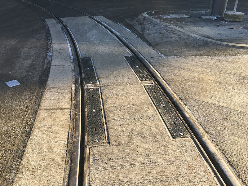
- Watertight inspection and hose connector boxesThese boxes are particularly suited for the subsequent installation of rail lubrication facilities. They are fitted with watertight covers in such a way that connections with the tracks or road drainage system are not needed and complex underground construction works therefore not required.
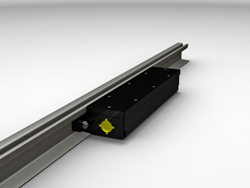
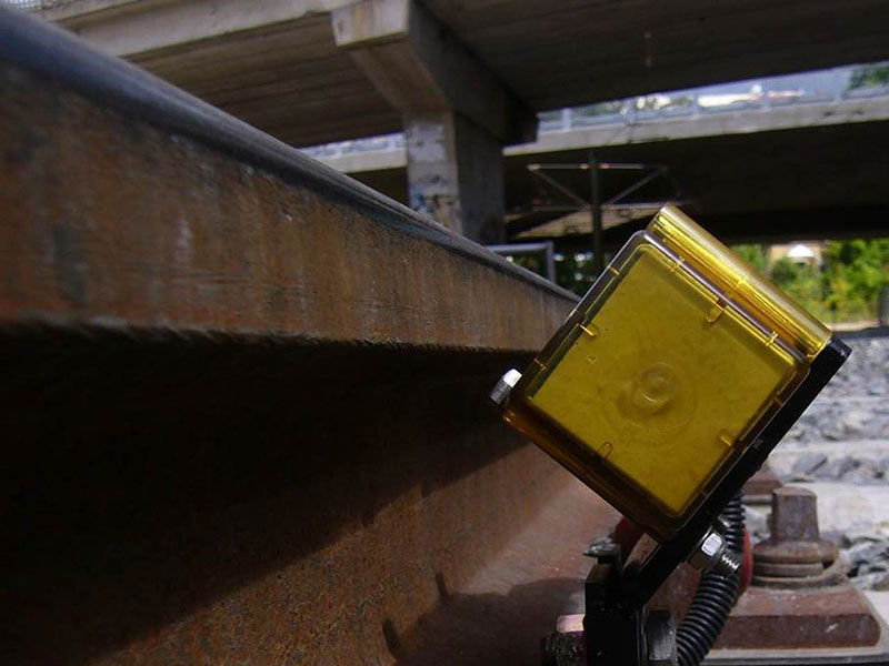
- Protective cover strips with track flange fastening systemLubrication paths in vignol and open grooved tracks are realized through protective cover strips. An open channel on the front side below the rail head absorbs the hose lines and distributor.
- Sensor connection box and sensor station for capturing running vehicle wheelsThey are fastened to the interior or exterior rails in different designs. Sensor connection boxes can be connected to the track drainage system for the deflection of surface water.